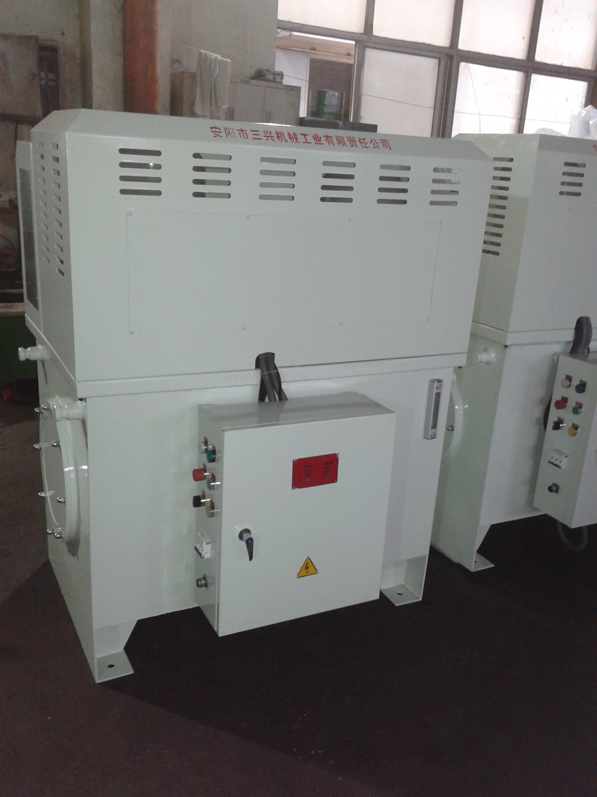
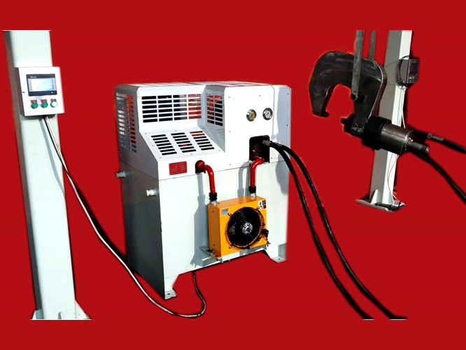
Hydraulic Riveting Machine
Sanxing Machinery has been serving customers for 26 years



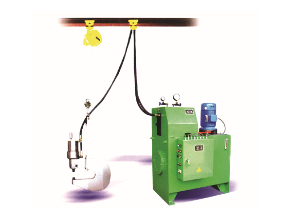
The hydraulic riveting machine is an indispensable core piece of equipment for riveting frames on all trucks, buses, and similar vehicles.
System Composition: The hydraulic riveting machine system includes a hydraulic power unit, riveting tongs, riveting dies, a lifting device, high-pressure hoses, a balancer, a trolley, and related accessories.
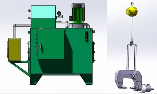
Hydraulic station suspended riveting pliers, lifting equipment, and spring balancers
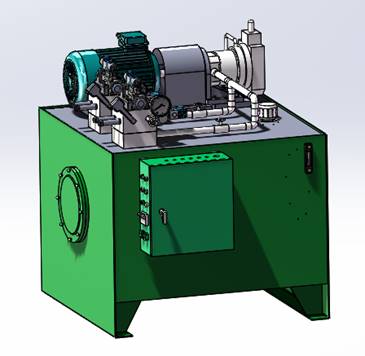
The direct-pressure riveting machine developed by our company uses a hydraulic power unit composed of a variable-displacement pump and a plate-type valve assembly. The hydraulic pump employs a high-performance variable-displacement piston pump with excellent characteristics. The hydraulic valves are from the reputable Rexroth brand. The key feature of this hydraulic power unit is that no pressure intensifier is required — the variable pump directly raises the oil pressure to the required high pressure. This design results in fast pressure rise, high riveting speed, simple structure, and easy maintenance.
The AX-50EB dual-system direct-pressure hydraulic riveting machine is developed by our company. Its maximum riveting force is 50 T, and the hydraulic system is a dual-circuit design (one active, one standby). The model designation is AX-50EB, where "50" indicates the maximum riveting force of 50 T, "E" indicates direct-pressure riveting, "B" indicates a standby circuit, and "EB" together indicates a dual hydraulic system with one standby circuit.
Nominal Riveting Force | 500 kN |
Power Supply | Three-phase, 4-wire, 380 V / 50 Hz |
System Pressure | 31.5 MPa |
Working Pressure | 31.5 MPa |
Adjustable Pressure | 50 T / 40 T / 30 T |
Riveting Cylinder Bore | Ø125 mm |
Riveting Cylinder Stroke | 90 mm |
Max. Cold-Riveting Diameter | Ø14 mm |
Riveting Rate | 20 ~ 35 cycles/min |
Motor Power | 11 kW |
Nominal Flow Rate | 90 L/min |
Cooling Method | Air-cooled heat exchanger |
Oil Tank Capacity | 1,100 L (dual system) |
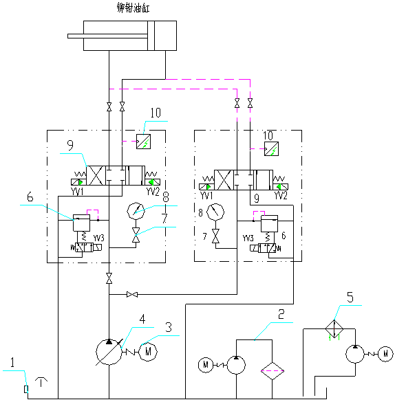
As shown in the hydraulic diagram, this machine adopts a high-pressure variable-displacement piston pump pressure-regulation system. During operation, the variable pump directly raises the pressure to 31.5 MPa. The relief valve in the system acts as a safety/unloading device. Key features include fast riveting speed, simple structure, and easy maintenance.
The 50 T dual-system direct-pressure hydraulic riveting machine assembly consists of six main components: oil tank, pump-motor assembly, hydraulic valve bank (two sets), cooling unit, bypass filtration unit, and electrical unit.
The pump-motor assembly, valve bank, and bypass filtration unit are all mounted on the tank cover for easy installation, adjustment, inspection, and maintenance. An open guard is installed on the tank, using a metal mesh structure to facilitate heat dissipation.
The oil tank is welded from Q235 steel plate. An air filter is mounted on the tank cover to filter both incoming oil and air. A baffle divides the return-oil chamber from the suction-oil chamber to promote oil circulation. A drain plug at the bottom allows the tank to be fully emptied, and a cleaning window at the end allows cleaning of the tank interior. A temperature-sensing level gauge on the tank monitors oil level and temperature.
The pump-motor assembly consists of a motor, a mounting bracket, a coupling, and a high-pressure piston pump. The pump-motor unit is mounted horizontally for easy adjustment. The pump and motor are connected via the bracket and a flexible coupling for easy assembly and replacement.
The hydraulic valve bank consists of hydraulic valves and a manifold block. All hydraulic valves are mounted around the manifold block — a simple structure with short oil passages, minimal leakage, and easy installation.
The hydraulic power unit is equipped with a dedicated bypass filtration system capable of fine filtration and water removal, greatly extending hydraulic oil service life and reducing hydraulic failures.
The pump and valve assemblies are fitted with open guards made from angle-iron frames and metal mesh for effective heat dissipation.
An oil cooler is provided to control hydraulic oil temperature.
Each hydraulic power unit is supplied with an oil drip tray. The tray extends 150 mm beyond the outer surface of the tank on all four sides, with rolled edges.
All hydraulic valves are Rexroth imported products and are interchangeable with Beijing Huade brand valves.
The riveting machine supports the following operating modes: inching, single-cycle, automatic, and release-to-return. Dual-operation and dual-pressure control allow one riveting machine to handle rivets of different specifications. PLC control is used with a touchscreen for pressure display. Pressure can be adjusted between 50 T, 40 T, and 30 T, and the adjustment time does not exceed 5 seconds.
The component configuration uses primarily internationally and domestically renowned brands — from hydraulic elements to tubing, fittings, and seals — representing a significant upgrade in quality. Key components: motor (SEW imported brand), hydraulic valves (Rexroth imported), cylinder seals (Hallite, UK), high-pressure tubing and fittings (domestic leading brands). This greatly enhances product performance and reliability.
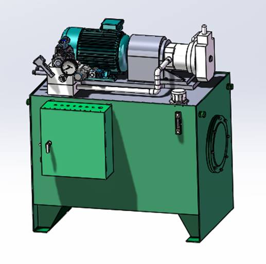
The AX-40E belongs to the same product series as the AX-50EB described above. Its maximum riveting force is 40 T, and it uses a single hydraulic circuit. The model designation follows the same convention as above.
Nominal Riveting Force | 400 kN |
Power Supply | Three-phase, 4-wire, 380 V / 50 Hz |
System Pressure | 31.5 MPa |
Working Pressure | 31.5 MPa |
Adjustable Pressure | 40 T / 30 T |
Riveting Cylinder Bore | Ø125 mm |
Riveting Cylinder Stroke | 90 mm |
Max. Cold-Riveting Diameter | Ø14 mm |
Riveting Rate | 20 ~ 30 cycles/min |
Motor Power | 7.5 kW |
Nominal Flow Rate | 60 L/min |
Oil Tank Capacity | 400 L |
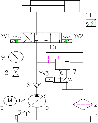
The hydraulic schematic is identical to that of the AX-50EB. It uses a high-pressure variable-displacement piston pump pressure-regulation system. The variable pump raises the oil pressure directly to 31.5 MPa during operation. The relief valve serves as a safety/unloading device. Key features: fast riveting speed, simple structure, easy maintenance.
The AX-40E assembly consists of five main components: oil tank, pump-motor assembly, hydraulic valve bank, cooling unit, and electrical unit — similar in composition to the AX-50EB.
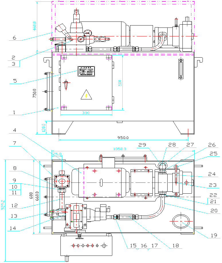
Same as Section 2.2.4.
Same as Section 2.2.5.
The pressure-intensified riveting machine uses a fixed-displacement pump that generates moderate pressure, which is then boosted by an intensifier cylinder to reach the high pressure required for riveting. Cartridge valves are used as control elements, offering large flow capacity and low heat generation. The drawback is a more complex structure — since the intensifier cylinder and manifold block are integrated, the manifold block is more difficult to manufacture. Control modes include: inching, single-cycle, release-to-return, timed pressure hold, dual-operation, and PLC control.
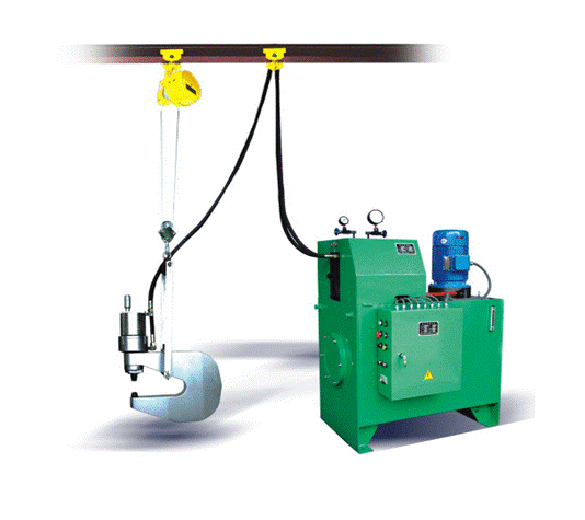
Main model series: AX30C, AX30CS, AX40C, AX40CS, AX50C, AX50CS (refer to company catalog for full specifications). The number indicates maximum riveting force (e.g., 40 = 40 T). "S" denotes dual-tong configuration, meaning one hydraulic power unit can drive two riveting tongs simultaneously.
Nominal Riveting Force | 400 kN |
Power Supply | Three-phase, 4-wire, 380 V / 50 Hz |
System Pressure | 6.3 MPa |
Working Pressure | 31.5 MPa |
Max. Cold-Riveting Diameter | Ø14 mm |
Riveting Rate | 20 – 25 cycles/min |
Motor Power | 7.5 kW |
Nominal Flow Rate | 60 L/min |
Oil Tank Capacity | 400 L |
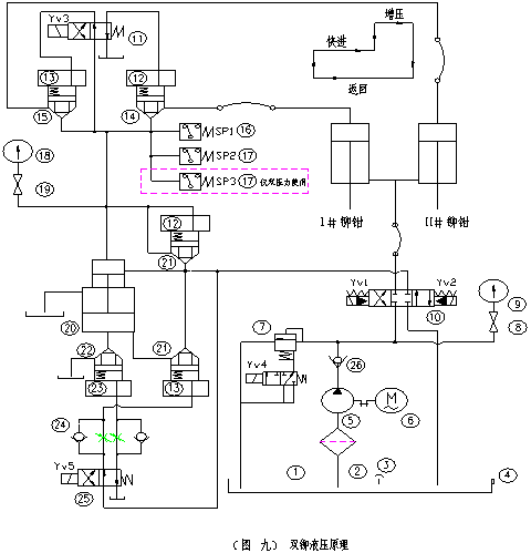
As shown in the hydraulic diagram, the system consists of a fixed-displacement pump, cartridge valves, and an intensifier cylinder. The intensifier principle is used to boost the output pressure of the fixed-displacement pump to the level required for riveting.
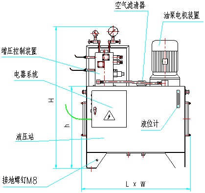
The AX-40CS assembly consists of five main components: oil tank, pump-motor assembly, hydraulic valve bank, cooling unit, and electrical unit.
Same as Section 2.2.4.
Same as Section 2.2.5.
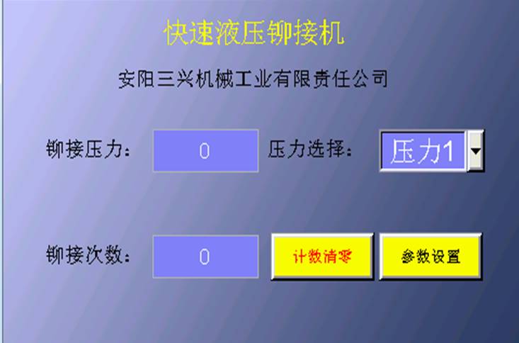
4.1.1 After the riveting machine is powered on, the touchscreen displays the main screen (Figure 1). The main screen shows the riveting pressure in use and the rivet count, along with a reset button to zero the count and a pressure selection combo button.
4.1.2 Press the count-reset button to zero the rivet count (Figure 1: Main Screen).
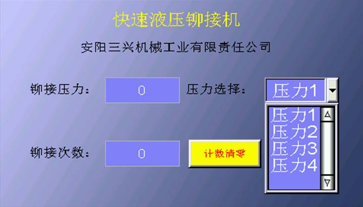
4.1.3 The riveting machine offers four selectable pressure levels (Figure 2: Pressure Selection).
4.1.4 Press the parameter-settings button to enter the parameter settings window (Figure 3: Parameter Settings).
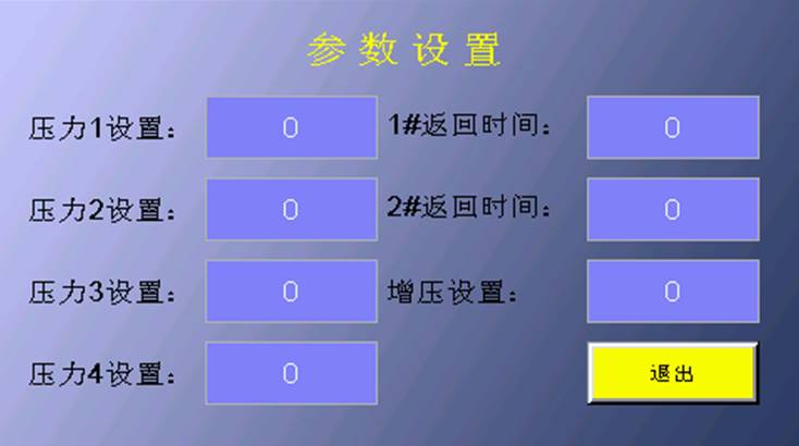
4.1.5 In the pressure setting input box, enter the required riveting pressure (5 – 30 MPa); in the pressure-boost setting input box, enter the boosting pressure (0 – 5 MPa).

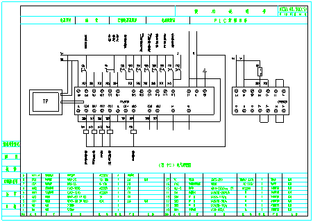
4.2 The electrical system is PLC-controlled. Dual-operation push-button stations can be added to columns near the workstation.
4.3 Inching function is provided to allow precise rivet alignment; release-to-return function is also included.
4.4 Short-circuit and overload protection for the motor.
4.5 The hydraulic power unit supports dual-tong structural configuration.
4.6 All electrical and hydraulic components are interchangeable.
4.7 Pressure-hold time after riveting is set via PLC.
4.8 Handle push-button control voltage: 24 V DC, ensuring personnel safety during maintenance and operation.

Alloy steel 42CrMo.
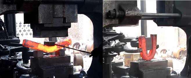 Integral forging + heat treatment.
6.2.2.1.1 Blanking
A: Blank (forging stock) weight formula: G_blank = G_forging + G_burning_loss + G_allowance + G_machining_allowance.
B: Cut the blank to the weight calculated from the drawing; tolerance not to exceed ±5%.
6.2.2.1.2 Heating
Material: 42CrMo. Initial forging temperature: 1,150°C; final forging temperature: 850°C. To ensure complete recrystallization and fine-grain microstructure after forging, heat the blank to 1,100°C and hold for 3 hours before forging.
6.2.2.1.3 Forging
A: After the soaking period reaches initial forging temperature, the blank is removed by a manipulator and forging begins.
B: Because the shape and dimensions of the forging are primarily controlled manually, repeated upsetting and drawing are performed to a certain size before the blank is introduced into the die and directly forged into the large bow form.
C: The number of heating cycles depends on blank size and process complexity; all forging must occur within the material's specified temperature range.
D: After auxiliary and finishing operations, the blank is forged to dimensions suitable for machining.
E: After forging, annealing is performed first; the part is then placed in a heat-retention pit for natural cooling.
Blanking → Free Forging → Die Forging → Inspection → Forming → Annealing → Planing/Milling → Inspection → Boring → Quenching & Tempering → Polishing → Final Inspection.
The tong body specification is designed based on the vehicle frame assembly model provided by the customer. Design factors to balance, in order of priority: compatible vehicle parameters, compatible rivet sizes, workstation operating envelope, and lightweight design.
Based on the design values, a stress analysis of the tong body is mandatory. Optimal stress values are assigned to each section to establish design baselines, and the final design is then derived from those baselines.
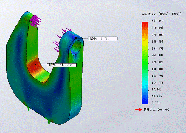
6.2.4.1 Vertical Riveting – Ø14 mm Rivets
Tong arm opening K = 210 mm; throat depth H = 250 mm; die shank diameter Ø25 mm. Cylinder stroke: 90 mm; bore: Ø140 mm.
6.2.4.2 Vertical Riveting – Ø12 mm Rivets
Tong arm opening K = 240 mm; throat depth H = 250 mm; die shank diameter Ø25 mm. Cylinder stroke: 90 mm; bore: Ø125 mm.
6.2.4.3 Horizontal Riveting Machine Basic Parameters
Arm opening H: 450 mm; throat depth h: 445 mm. Height of arm rivet-seat centerline above floor: 1,000 mm. Die shank diameter: Ø25 mm. Cylinder stroke: 150 mm; bore: 140 mm.
6.2.5.1 Applicable Standards
Design, manufacture, testing, inspection, and installation of the riveting equipment shall strictly comply with standard JB/T9966-99. Anyang Sanxing Machinery Industry Co., Ltd. was honored to participate in the drafting of this standard.
6.2.5.2 Referenced Standards
GB 5226-85 Technical Conditions for Machine Tool Electrical Equipment
GB 3766-83 General Technical Conditions for Hydraulic Systems
GB 181 Packaging and Storage Pictorial Marking
GB 116 Technical Conditions for Rivets
GB 699 Quality Carbon Structural Steel Grades and General Technical Conditions
JB 1885-77 Type-A Crimp-Sleeve Hose Fittings
ZBJ50011-89 Technical Conditions for Machine Tool Painting
ZBJ50013-89 Technical Conditions for Machine Tool Rust Prevention
ZBJ50014-89 Technical Conditions for Machine Tool Packaging
GB 17120-2012 Safety Technical Conditions for Forging and Pressing Machinery
GB/T 7935-2005 General Technical Conditions for Hydraulic Components
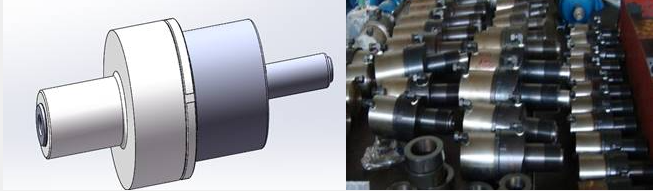
The riveting cylinder is one of the core components of the riveting machine.
The cylinder head and matching nut are both forgings, conforming to forging process requirements.
The cylinder bore inner wall is roller-burnished to increase material density while simultaneously improving surface finish.
No. | Part Name | Material | Notes |
1 | Riveting Tong Body | 42CrMo | Integral die forging |
2 | Riveting Die | 42CrMo | Quench-hardened |
3 | Riveting Cylinder | 45# forging | Bore roller-burnished |
4 | Oil Tank | Q235 weldment | Passivated; weld seam inspection |
5 | Piston Rod | 42CrMo forging | Chrome-plated surface |
6 | Electrical Control Box | Q235 weldment | Electrostatic sprayed; IP50 rated |
8.1 Gap between plates after riveting: ≤ 0.02 mm.
8.2 The mating surfaces of riveted parts shall be in tight contact; the tight-contact diameter shall be no less than 3 times the rivet shank diameter.
8.3 At least one point around the perimeter of the rivet head shall be in contact with the workpiece — a 0.05 mm feeler gauge shall not penetrate at that point; elsewhere, a 0.25 mm feeler gauge shall not penetrate.
8.4 Rivets shall not be inclined; rivet shank offset shall not exceed 0.4 mm.
8.5 The rivet shall fill the rivet hole satisfactorily. Gaps between the rivet head and the riveted surface, between mating surfaces, and between the formed head and the riveted surface shall not exceed 0.05 mm. The formed head shall be free of cracks.
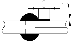
8.6 Rivet head flange flash requirements: C < 2 mm; D < 1.5 mm (see figure).
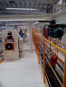
The hydraulic power unit is placed on a steel-structure platform above the work floor. Power is supplied via cable tray conduit. This centralized placement facilitates maintenance management while saving floor space. The hydraulic power unit has an operator panel for maintenance use; an additional operator panel is also mounted on a column below for production worker use.
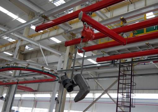
The riveting tongs are suspended on KPK rail tracks beneath the steel structure. Via trolley and balancer, they can be freely raised, lowered, and moved to any position.
There are generally two layout methods for the high-pressure tubing between the hydraulic power unit and the riveting tongs:
Method 1: High-pressure rigid tubing exits the hydraulic power unit with a bend and runs down along the steel structure to a position below the platform. Compression fittings are used to connect flexible hose to the riveting cylinder. The rigid tubing is Ø25 mm seamless steel pipe with rust-proof treatment, secured with tube clamps and fixed to the steel structure.
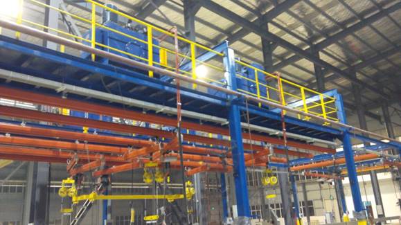
Method 2: The high-pressure rigid tubing passes through the steel structure platform and runs downward; all other connections are the same as Method 1.